|
CLAY DIVIDER CAE Auto-meshing
Generator CLAY DIVIDER for Windows NT 4.0 and Windows2000
Dramatically Improves Processes
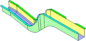
When auto-meshing a three-dimensional shell element, a group of CAD surfaces are automatically recognized as a single zone (virtual zone). A mesh is generated for each zone. This method drastically reduces the amount of meshing process. A number of mesh patterns are provided for flexible mesh generation according to the type of analysis and shape. |
 |
 |
|
| Operation Flow |
 |
Three-dimensional
CAD
IGES, SAT
CATIA, etc. |
Reading basic shapes |
 |
 |
| Initialization |
Initialization
for creating a virtual zone
- CAD gap setting - Inter-face angle |
 |
 |
| Auto
Virtual Zone |
- Automatically
recognizing CAD surfaces, outer diameters, and zone
directions
- Selecting mesh patterns
- Basic element size
- Minimum element size

(CAD surface recognized in auto virtual zoning) |
 |
 |
|
Specifying a Feature Line Selecting a Hard Line |
- Specifying and generating for each virtual zone |
 |
 |
| Selecting Hard Points |
(Arbitrary) |
 |
 |
| Auto-meshing |
- Turning on or off re-meshing |
 |
 |
| FEM Mesh Completed |
 |
 |
 |
| FEM Mesh Editing |
-
Morphing
- Enhanced re-meshing
- Model Editing |
 |
|
 |
To
requesting a product catalog, please send an e-mail to info@ftr.co.jp.
You can freely download the online catalog in PDF format.
This catalog is copyrighted by Fuji Technical Research Inc.
All rights reserved. |
|


